
CNC design is an integral part of CAD/CAM technology. You use these drawings for the development and production of a product.
However, engineering drawings are complex. They are full of symbols, abbreviations, and strange phrases that you may not be able to decipher. This is where the meanings behind these various pieces come in handy!
While you may understand the basic terms such as KG and CM, it becomes more difficult when you come across terms such as CYL and EQUI SP. If you have found it tough to interpret CNC designs, we’ve got your back!
We have prepared an extensive list of engineering drawings abbreviations and symbols for you to reference. Read on.
Benefits of Using Abbreviations and Symbols in Engineering Drawings
The design of an engineering drawing is critical. The abbreviations and symbols used must be concise. They should provide all the necessary information to produce a CNC milling part without a hassle.
Because there is no room on your image for text, symbols & abbreviations are relatively less overwhelming. When well used, they result in clean and uncluttered images, allowing the viewer to grasp all important aspects of your design.
To further aid comprehension of what is on paper, abbreviations and symbols must be accurate. One typo can lead to serious consequences like making something too heavy. So make sure you understand them well!
Are Engineering Drawing Abbreviations and Symbols Standardized?
As with other engineering terms, abbreviations and symbols are subject to standardization. In the United States, the majority of these terms follow Norms ANSI or ASA. ASME handles some specific ones related to mechanical engineering.
Other international engineering standards include ISO, AS (Australia), AFNOR (France), USA (AISI, ASTM, AMS, ANSI, and SAE), AFNOR (France), UNI (Italy), KS (Korea), Germany (DIN and WR), JIS (Japan), SS (Sweden), and BS (UK). You should note that an abbreviation can have different meanings in different categories.
In addition to these worldwide standards, each design firm has its own set of requirements. As such, you should check what your company’s preferred abbreviations and symbols are.
Common Engineering Drawing Abbreviations
There are numerous abbreviations and symbols in various engineering drawing categories. You can use this guide as a reference to help you decipher what is written on your engineering drawing. Also check GD & T symbols and terms here.
Here’s the complete list of abbreviations and symbols in alphabetical order for easy reference:
| AF: Across Flats | HEX HD: Hexagon head | MM: Millimeter |
|---|---|---|
| Ą°: Degree (of angle) | HEX: Hexagon | NO.: Number |
| ASSY: Assembly | HRA: Hardness Rockwell A scale | NTS: Not to scale |
| CĄŻBORE or CBORE: Counterbore | HRB: Hardness Rockwell B scale | O/D: Outside diameter |
| CH HD: Cheese Head | HRC: Hardness Rockwell C scale | PCD: Pitch circle diameter |
| CHAM: Chamfered | HRD: Hardness Rockwell D scale | QTY: Quantity |
| CL: Center line | HRE: Hardness Rockwell E scale | RAD or R: Radius |
| CM: Centimeters | HV: Hardness Vickers | RD HD: Round head |
| CSK HD: Countersink Head | HYD: Hydraulic | RH: Right hand |
| CSK: Countersink | I/D: Internal diameter | RPM: Revolutions per minute |
| CYL: Cylinder or Cylindrical | IN: Inch | SCR: Screwed |
| DATUM: Datum System | INSUL: Insulated, insulation | SK: Sketch |
| DIA: Diameter | INT: Internal | SPEC: Specification |
| DIM: Dimension | JT: Joint | SPH: Spherical |
| DRG: Drawing | KG: Kilogram | SQ: Square |
| ENG: Engine, engineering | LB: Pound | STD: Standard |
| EQUI SP: Equally Spaced | LG: Long | SWG: Standard wire gauge |
| EXT: External? | LH: Left hand | THD: Thread |
| FIG: Figure | M/C: Machine | TPI: Thread per inch |
| FT: Foot | M: Meter | VOL: Volume |
| GAL: Gallon | MATL: Material | WT: Weight |
| GALV: Galvanized | MAX: Maximum | |
| HB: Hardness Brinell | MIN: Minimum, Minute? |
More engineering drawing abbreviations can be used in CNC manufacturing, including:
| AC: Across corners | CNC: Computer Numerical Control | PC: Piece |
|---|---|---|
| ALY: Aluminum | CRES: Corrosion-resistant | PD: Pitch diameter |
| ANN: Anneal | DIM: Dimension | PL: Parts list |
| AQL: Acceptable quality level | ED: Edge distance | PMI: Product and manufacturing information |
| AR: As required | IAW: In accordance with | REF: Reference |
| AVG: Average | LMC: Least material condition | RZ: Roughness, mean depth |
| BASIC or BSC: Basic dimension | MBP: Measurement between pins | SFACE: Spotface |
| BC or B.C.: Bolt circle | MBW: Measurement between wires | SN: Serial number |
| BHC: Bolt hole circle | MFD: Manufactured | STD: Standard |
| BRZ: Bronze | MFG: Manufacturing | UNC: Unified National Coarse |
| CAD: Computer-aided design | MFR: Manufacturer | UNS: Unified National Special |
| CERT: Certification | MMC: Maximum material condition | YS: Yield Strength |
| CI: Cast iron | OAL: Overall length |
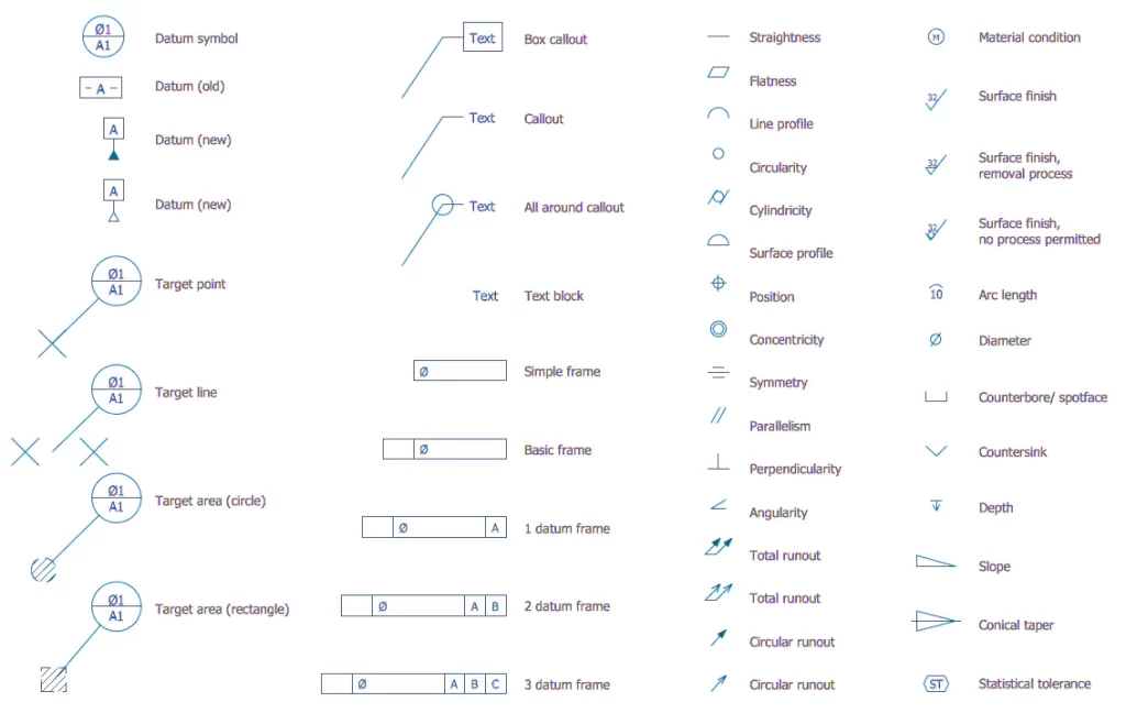
Engineering Drawing Symbols
Besides the abbreviations, CNC and engineering drawings also feature symbols. They describe various components and how each part should be made.
Engineering drawing symbols represent views of several geometry types such as surfaces (flat, cylindrical, spherical & toroidal), lines (linear, reference & centerlines), points (center & intersection), and also some standard views for orthographic projections, section view, and auxiliary views.
In the picture below, you can see a list of the most used engineering drawing symbols:
Additionally, different software packages have different sets of symbols available to create a drawing. At times, you may modify an existing one or create your symbol. However, it’s best to stick with the standard symbols, that way you will avoid interoperability issues.